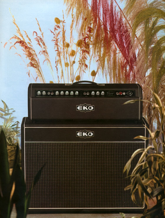
WHEN IT ALL BEGAN
In 1990 while I was throwing away some garbage in a junk yard I found this Eko Viscount Reverb laying in the mud. I saw the tubes inside and so I took it home thinking that sooner or later it might have become useful. In 2008 my 12 years old nephew felled in love with guitars and as a present for his birthday we all gave him a classic guitar. For the future he is thinking about an electric guitar. So after 18 years of waiting that old amplifier finally became useful!!!
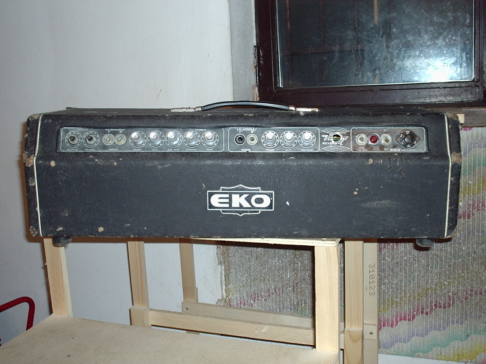
As you can imagine, when I took it from its storage it was a little dusty, I cleaned it and here are some pictures.
Front and back
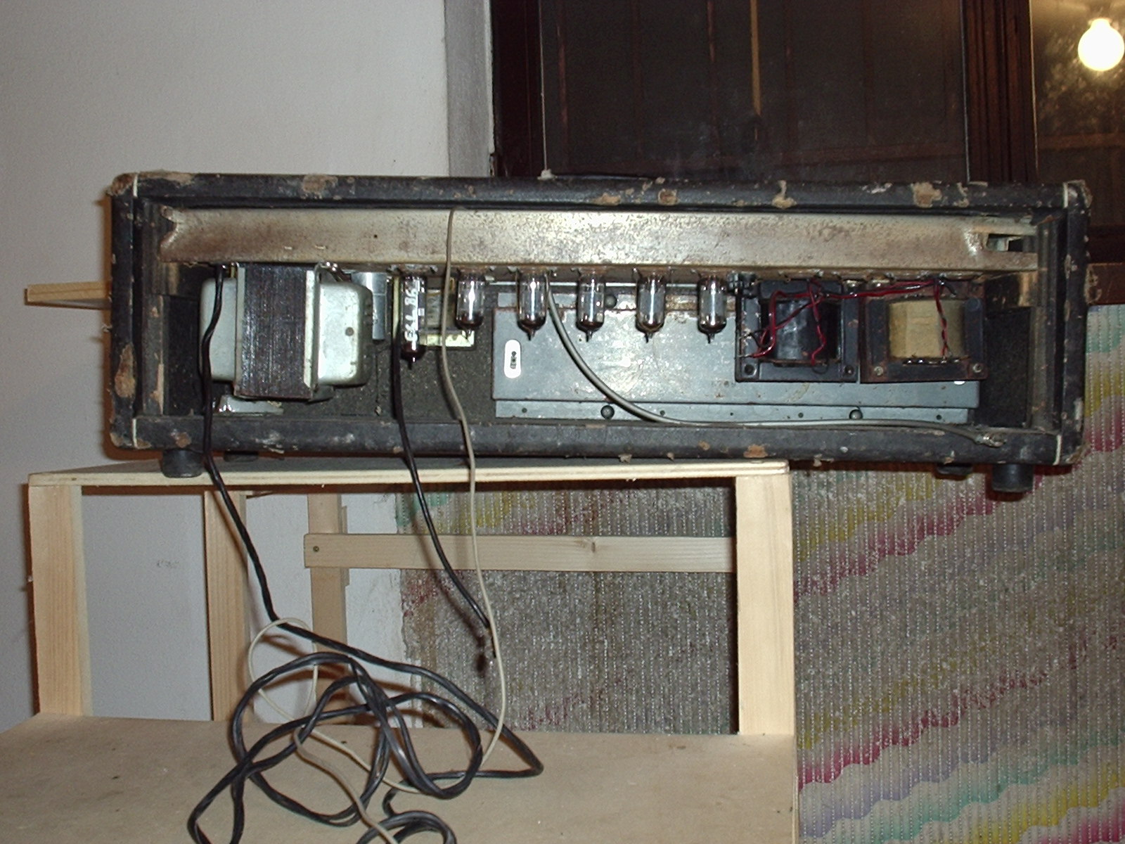
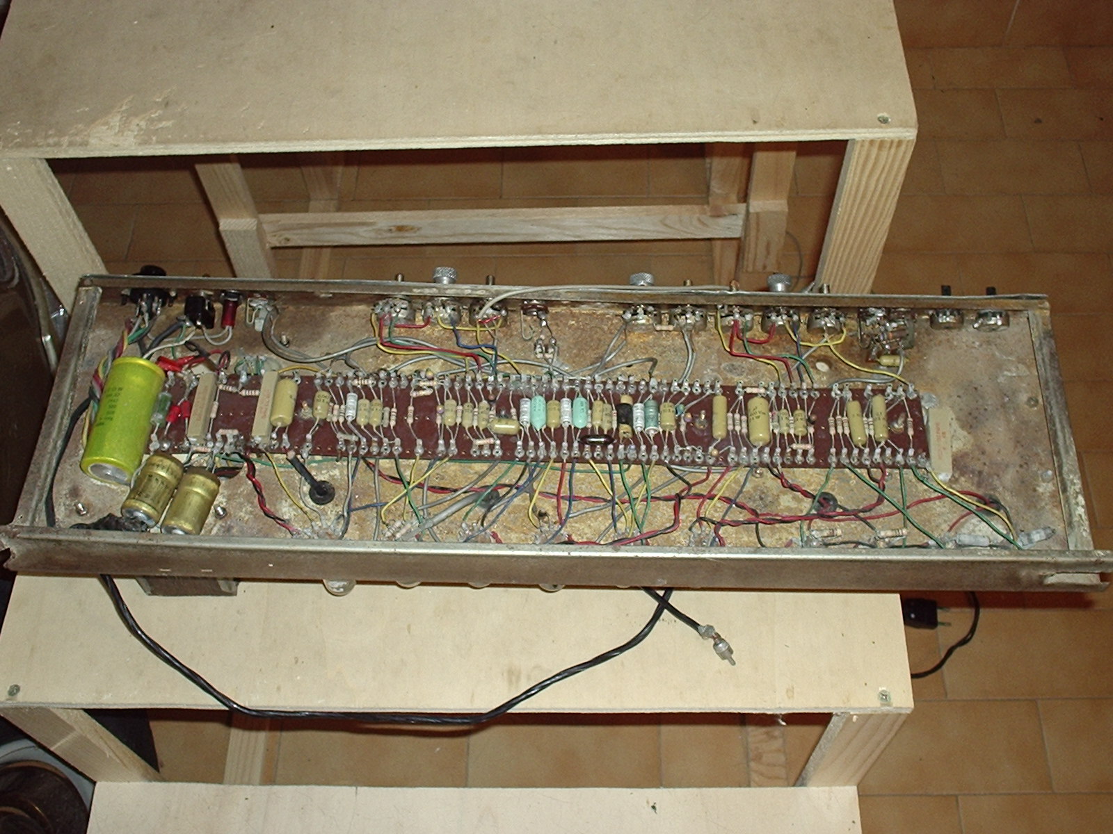
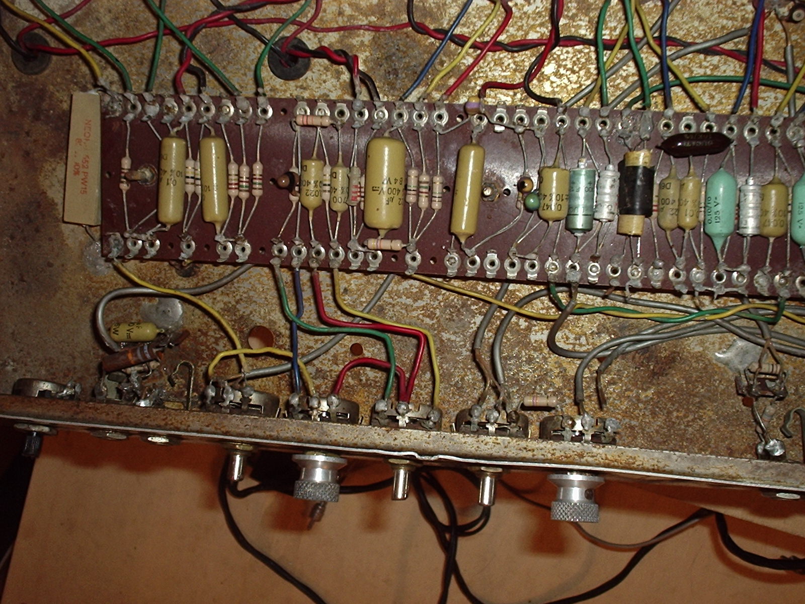
Inside
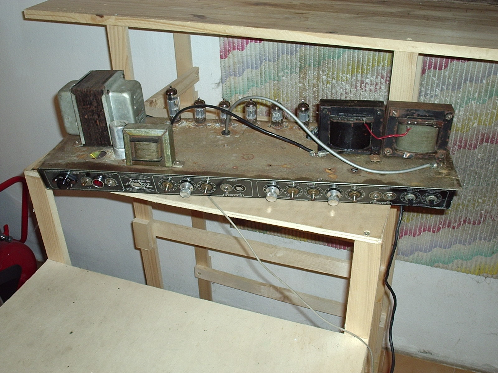
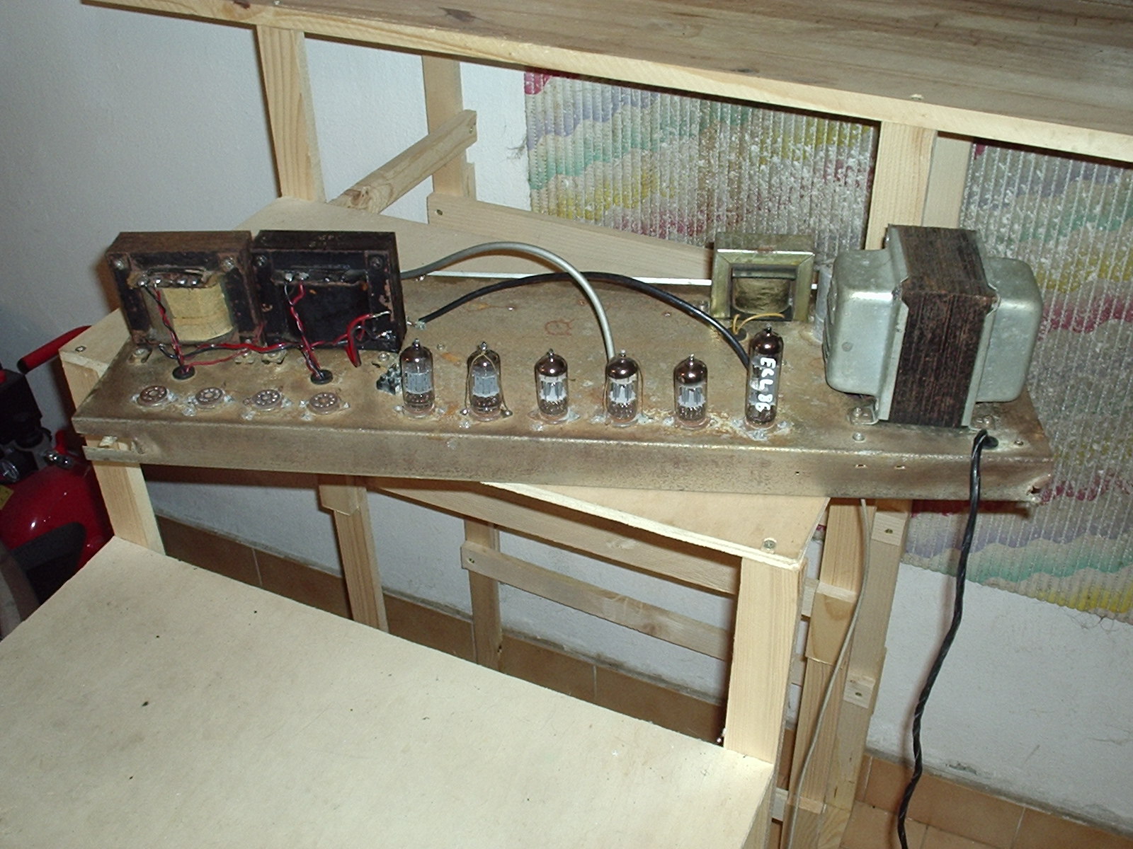
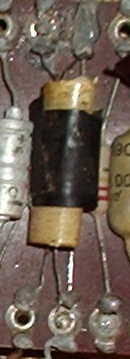
A couple of views of the electronics
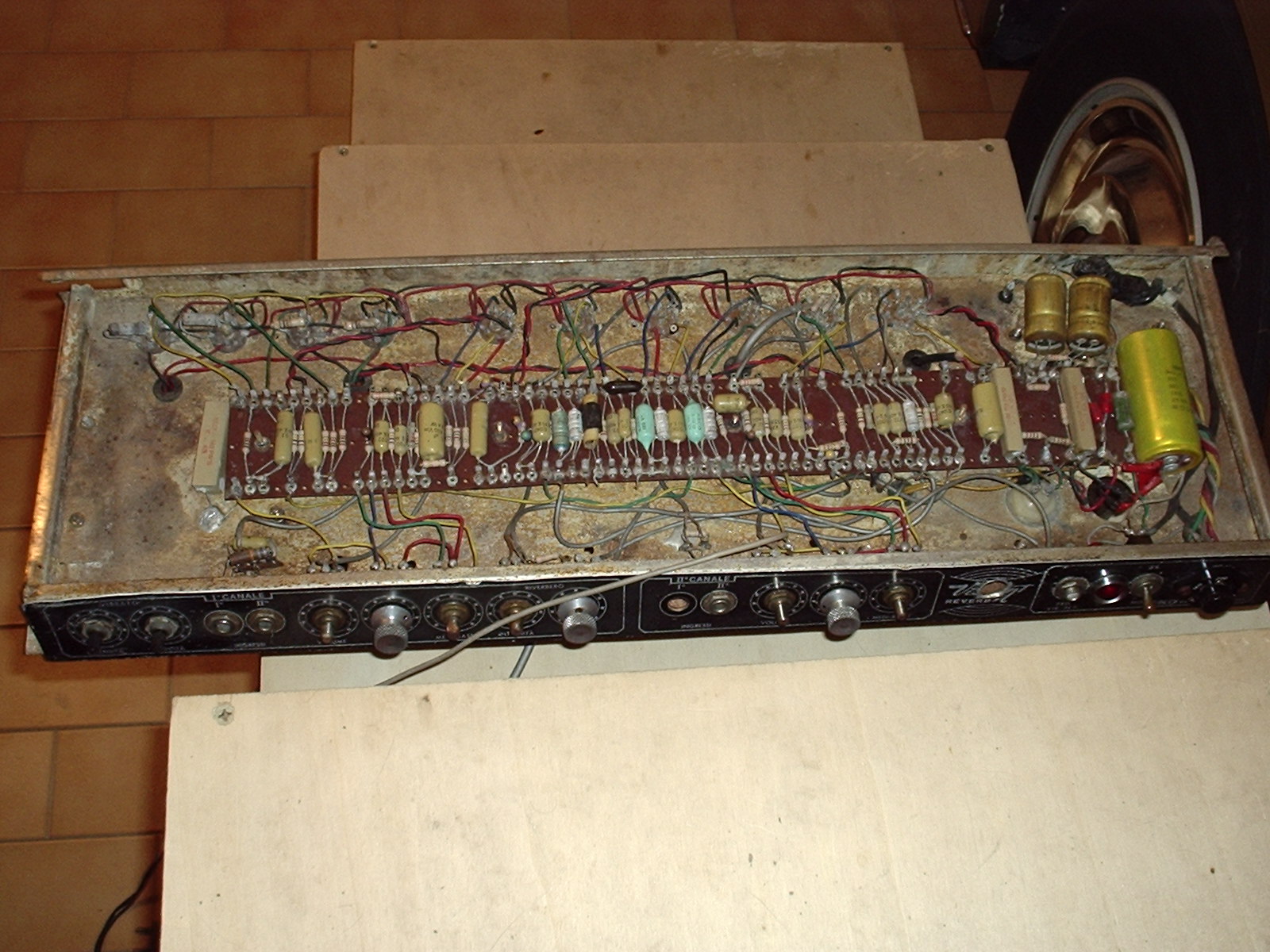
At the end of the restoration it will look much better, with fixed chassis and electronics and with new tolex for the outside.
CHANNEL 1 INPUT + VIBRATO CONTROLS
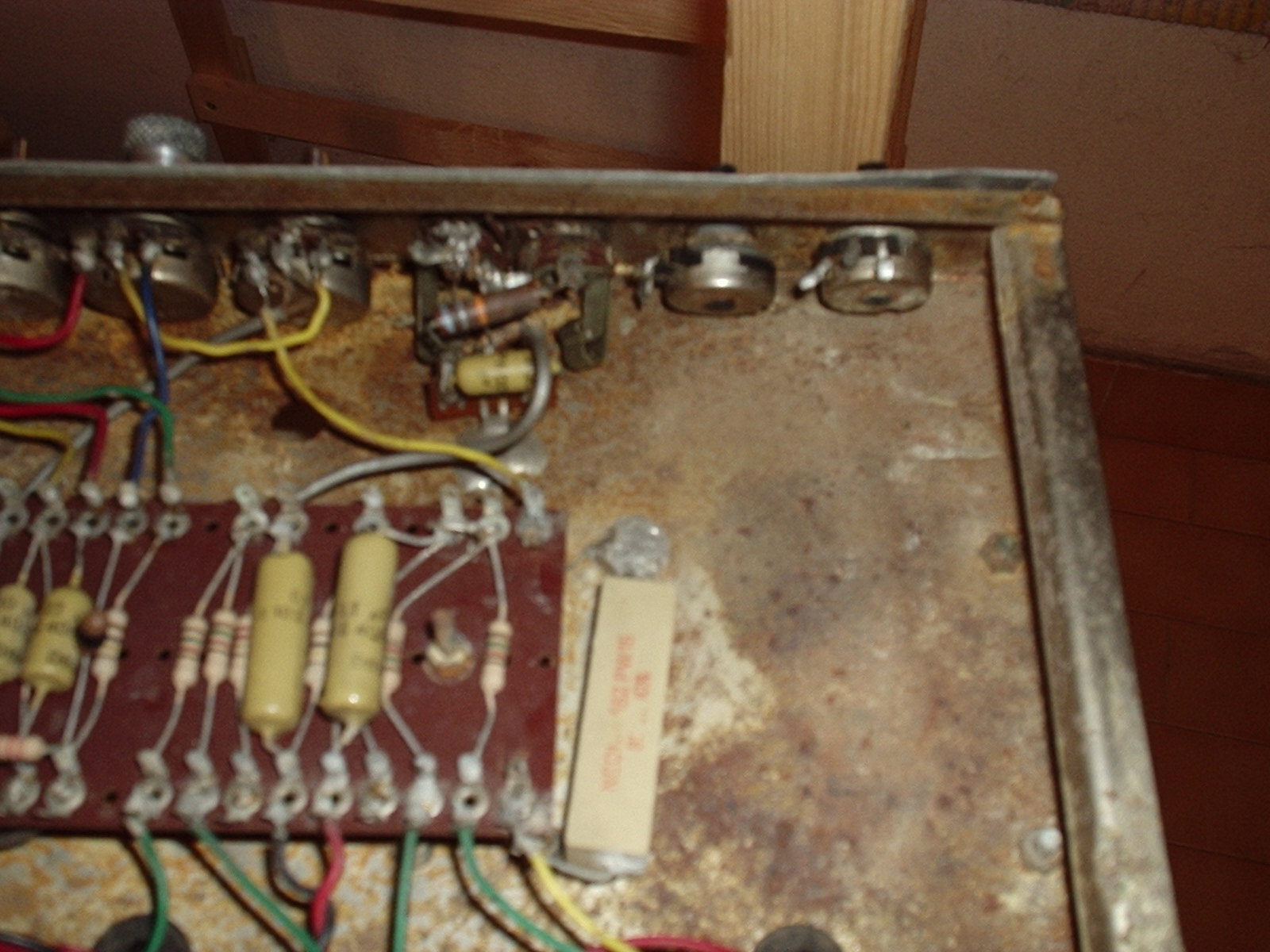
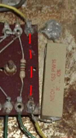
In this amp unfortunately all the wirings of the vibrato circuit have been cut away, only the tube and the components have been left on the board… luckily!!! Here are some close views of channel 1 input and of the two vibrato controls wired to the surrounding air.
Controls and electronics
The two vibrato controls are not original, probably they have been changed because the original ones did not work anymore, but this seems strange to me, I would bet that the volume control, that are still the original ones, would fail sooner than these. Otherwise they have been changed because another electronic circuit was fitted inside this amp. This possibility seems to be much closer to reality also due to some modifications done to the chassis (holes and cuts). In this case I suppose that even the values of the controls fitted in the amp are not the correct ones.
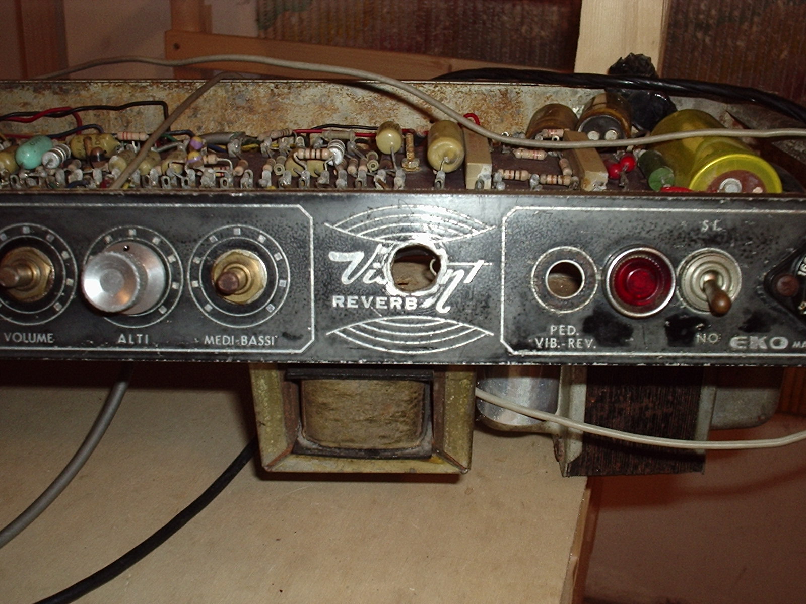
A NICE HOLE!
And now something about cosmetics. Someone decided to add another input jack and then he/she removed it leaving a very nice hole just in the middle of the Viscount logo. Really attractive, isn’t it? I’ll try to reproduce the missing part.
SCHEMATIC DIAGRAM
The electronics of the Eko Viscount Reverb are not complicated apart from channel 1 that has also the vibrato and the reverb effects. For simpler reading I’ve divided the schematic in four sections:
– Power supply
– Channel 1 (Canale 1)
– Channel 2 (Canale 2)
– Power amplifier
TUBE NAMING CONVENTION
I named the tubes starting from the first EL84 (V1) on one side going to opposite one where the ECL86 (V10) is placed. Here are the tubes, the names used in the schematic diagram and their function in the amplifier.
V1 – EL84 – power output
V2 – EL84 – power output
V3 – EL84 – power output
V4 – EL84 – power output
V5 – ECC83 – phase inverter and driver
V6 – ECC83 – low frequency oscillator and neon bulb driver (vibrato effect)
V7 – ECC83 – channel 1 second and third preamp
V8 – ECC83 – channel 2 first and second preamp
V9 – ECC83 – channel 1 first preamp; reverb first preamp
V10 – ECL 86 – reverb second preamp (triode); reverberation unit driver (pentode)
POWER SUPPLY
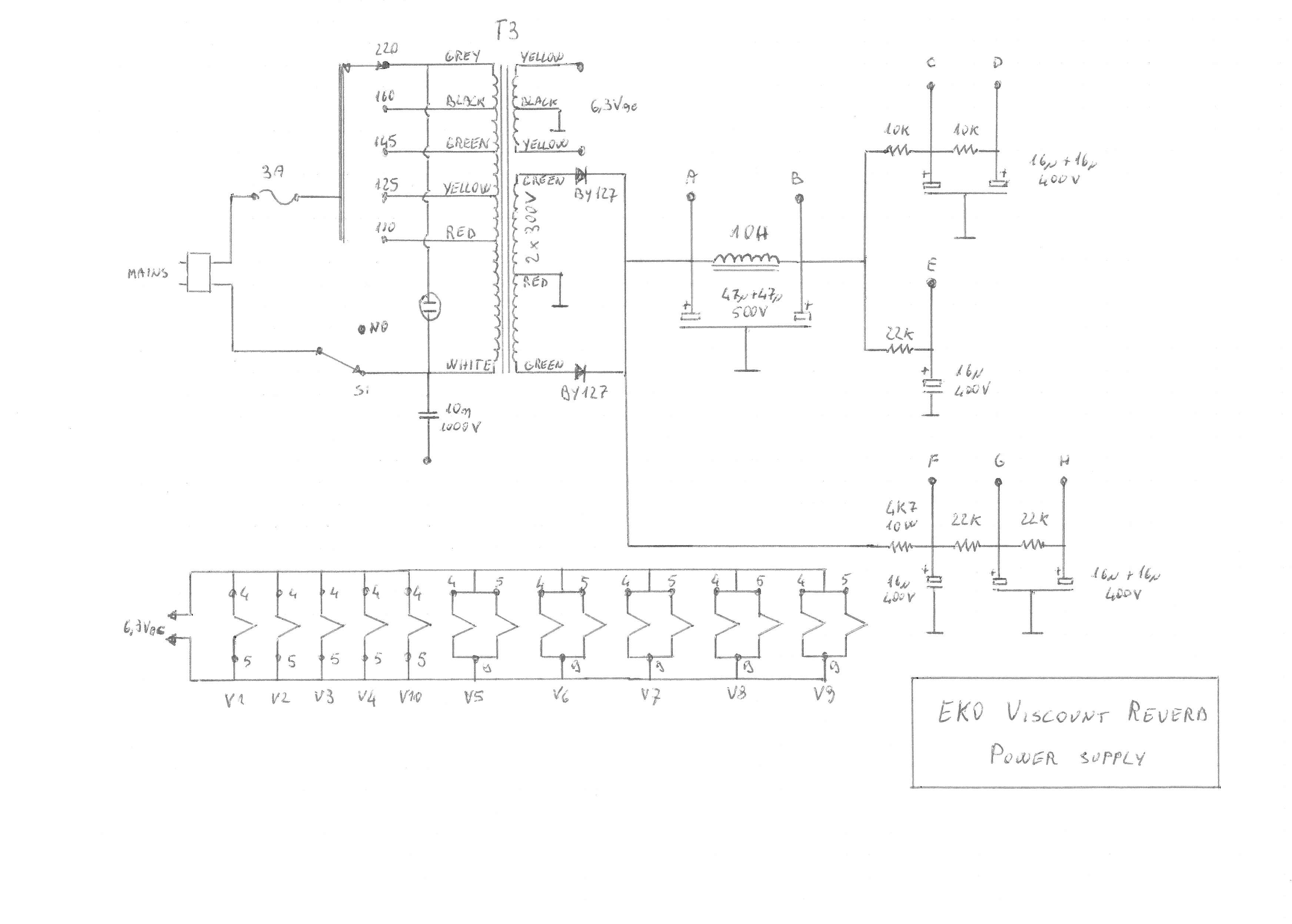
Let’s begin with the simplest stage, the power supply. The mains power goes to the primary winding of the power transformer through a voltage selector and, of course, through the mains switch. The fuse is installed inside the knob of the voltage selector on the front panel. As you can see there is also a capacitor between the output of the mains switch and a pin installed on the chassis. This, if too much hum noise is experienced, can be connected to the chassis (ground). In many amplifiers of the 60’s this was a common solution to hum noise, but actual safety regulation prohibit this kind of workaround. In such a way the chassis is partially connected to mains, but the chassis is also the signal ground and so also everything connected to the amplifier will be partially connected to mains: instruments and other electronic equipment. If that capacitor fails (i.e. short-circuits), ground is DIRECTLY connected to mains and so all the rest. VERY UNSAFE!!! I will definitely remove that capacitor and I will connect the chassis to ground (earth) with a 3 wires power cable (standard one). Ground connection should remove all hum noise.
The power transformer has two secondary windings:
– 6.3V, with a center tap connected to ground for hum balancing, that feeds the heaters;
– 2 x 300V (approximately) for the anodic supply (high voltage).
The high voltage is rectified by two solid state diodes (BY127) and then goes to two main filtering cells:
– an LC that feeds the power amplifier (point A anodes, point B screen grids), these are the points at highest voltage and lowest output impedance;
– an RC followed by other two feeding the reverb circuit (points F, G and H).
At the output of the LC we have other RC cells:
– one for the vibrato circuit (point E);
– two in series for the preamplification stages (points C and D)
This is a very nice layout, every stage has its own decoupled power supply line, there is no mutual interference at power supply level. I like it very much!
And now a little note for restoration. All the electrolytic capacitors are “vintage”, mine are dated 2/67. It is suggestible to change all of them, this is true for every “over 30” electronic equipment. Old capacitors have the “nice” habit of short-circuiting and sometimes they even explode! In the occasion I will increase their values:
– the 47uF + 47uF 500V (points A and B) will be replaced by a 100uF + 100uF 500V;
– the 16uF + 16uF 400V (points C and D) will be replaced by a 50uF + 50uF 400V;
– the 16uF + 16uF 400V (points E and F) will be replaced by a 32uF + 32uF 400V;
– the 16uF + 16uF 400V (points G and H) will be replaced by a 32uF + 32uF 400V.
After the tests I decided to add a “pop suppressor” in parallel to the mains switch to avoid the “pop” when turning the amplifier off.
CHANNEL 2
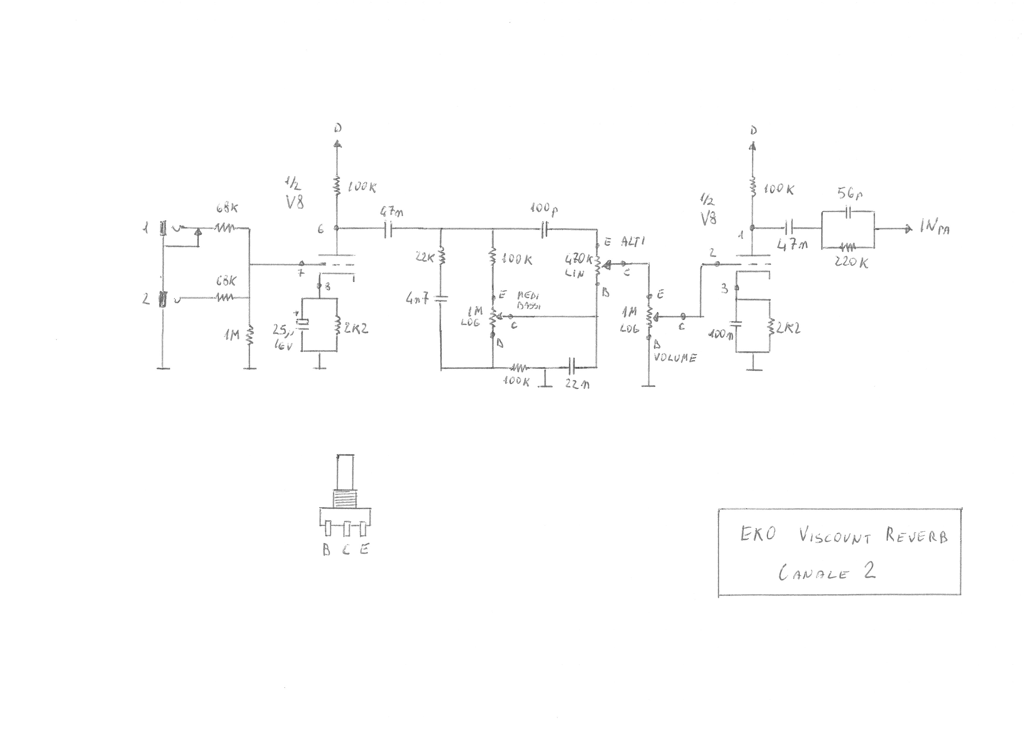
This stage is very simple, it has two gain stages with the tone and volume controls between them. There are two inputs:
– 1 high gain
– 2 low gain
The signal then enters the first gain stage, a standard common cathode circuit, then it goes into the passive tone control network. We have two separate controls, one for basses and mids, the other one for highs. The linearity of this network is for me a real pain in the neck: with both control knobs set to mid position the output is everything but linear. First of all the bass/mid potentiometer is not a linear one, but it is logarithmic, so at mid position, looking at the resistances from the cursor side, we have one half of roughly 150K and the other of 850K. This leads to not having a flat response at mid position. Actually the flattest overall (from signal input to power output) is achieved, in a simulation with the computer, with the bass+mid at minimum position and with the high slightly before the mid position. Moreover, moving the bass+mid control fully clockwise (maximum position) a hole of about 20dB is created around 700Hz. This means that when notes near that frequency (please don’t ask me which notes!) are played with a guitar with such a setting of the tone controls cannot be heard at all. Well this is just a simulation, I will check as soon as I will have the amplifier working, but if it will be confirmed I will rework this network to have a more linear behavior.
The output of the tone control network is fed to the volume control then the signal another amplification stage similar to the first one but the decoupling capacitor paralleled to the cathode resistor this time is 100nF and not a 25uF as in the first stage. This leads to a different amplification for basses + mids and for the highs where the gain is higher. I suppose that this is the first attempt to make the overall frequency response more linear. Another attempt is found in the power amplifier stage. At the output of this stage we find a high frequency compensating network that goes to the power amplifier output. That’s all for channel 2.
CHANNEL 1

Well it really looks complicated. This channel apart for amplifying the input signal it also adds the vibrato and the reverb effects. Let’s see how it works. We have the usual high (1) and low (2) gain inputs that go to the first amplification stage. This one is a little different from the one employed in cannel 2. The bias of this stage is achieved through the grid current flowing in the 4.7M resistor connected between the grid and ground and decoupled from the input by the 22nF capacitor. This was a common way of biasing small signal tubes… well I’ve never been able to understand the benefits: compared to the usual common cathode layout we can only save one resistor. What a saving!!! But we gain more noise generated by the high value grid resistor. But this is how it was engineered, let’s keep it this way. At the output of this stage we find a big mess! Well, not really. We have a passive divider that is connected to the vibrato circuit and also to the second amplification stage, then we also have a high pass filter that feeds the reverb circuit. Let’s begin with this one. The reverb has three basic components: a power amplifier (1) that drives the reverberation unit (2) whose output feeds another amplification stage (3). The power amplifier is implemented using the power pentode contained inside the ECL86, it is connected in triode mode and the decoupling cathode capacitor is of relatively small value to have a higher gain at high frequencies: this is OK, it is part of the reverb effect. The reverberation unit is a 4 spring type, it is a Gibbs/Hammond type 4 unit (still in production as I’ve read in the internet). The output of this unit feeds an amplification stage that drives a passive tone control network, then we have another amplifier to regain what has been lost in the tone control circuit. The output goes both to the reverb/vibrato pedal (for enabling/disabling this effect) and also to the intensity (volume) control.
The other effect is the vibrato one. Actually it modulates a signal in accordance to a low frequency (adjustable) oscillator. All the circuit drawn is the original one, but the two potentiometers that set the speed/frequency and intensity where missing in my amplifier, so searching the internet for other amplifiers employing such an effect with the same circuit I deducted their values. The speed (velocità) control value is not critical, it just sets the frequency of the oscillator, if its value is too small the frequency will be slightly higher that the original one, on the other side if its value is too high the frequency will be lower then the original one. I preferred to have a slightly high value to achieve a wider frequency range. I also put in series to the potentiometer a resistor, this sets the highest frequency for the oscillator, in this case is around 12Hz. In this circuit we have two stages: the low frequency oscillator and the neon bulb driver, all implemented using one ECC83 (V6). I quote a very nice and detailed description of the oscillator I found in internet
—
The vibrato oscillator is simply a phase shift oscillator. … What makes an oscillator? The answer is an amplifier with positive feedback. Negative feedback (180°), will reduce the gain of an amplifier. That is how opamps work. They are near infinite gain amplifiers and negative feedback is applied to “tame” the gain to the desired value. Another example of negative feedback is the PRESENCE control of a tube amp. It feeds back the output signal into the power amp input 180° out of phase, but only the low frequencies. This reduces the low frequency gain. Positive feedback causes oscillation. This is achieved in the circuit below by using three resistor capacitor networks. A pure capacitive network is a 90° phase shift. The series capacitor and shunt resistor network in this case provides about 60° of phase shift. Since the tube amplifier output to input is 180°, following the output with three 60° RC networks (3 x 60 = 180), results in 360° of phase shift, which is positive feedback. … The other part of the circuit is the tube that drives the opto-isolator. The opto-isolator is nothing but a neon lamp in heatshrink tubing with a light dependent resistor (LDR).
If the light is on, the resistance is low. If the light is off, the resistance is high. The LDR is shunted across the vibrato channel output, and effectively amplitude modulates the signal. The intensity control applies the LDR to the signal, or shunts it more to ground, causing less vibrato.
—
The network connected to the cathode of the neon bulb driver goes to the vibrato/reverb pedal, when it is ground connected (it is by default because of the switch installed in the front panel jack) current flows in the triode and, of course, even in the neon bulb, so the effect is engaged, when the network is not connected to ground (switch open) no current flows and the effect is disengaged. The LDR is connected to the intensity control whose cursor is linked to the first amplification stage output passive divider (part of the mess I was talking about before) and also to the output of the reverb effect where we have another passive divider. So the vibrato is applied to both the signal of the guitar and to the reverb. This looks correct to me. The impedance seen by the passive dividers is that of the LDR that continuously follows the oscillator, so also the attenuation of those passive dividers changes accordingly to the oscillator. Simple! The overall gain of this mess is approximately 1, no gain! So we have another amplifier, identical to the one employed in channel 2, apart from a little high frequency compensation at the input (the 100pF capacitor between the anode and the grid of the first triode) and the network at the output, probably compensating the different behavior of previous circuits.
A little note about the vibrato intensity control. The value of this potentiometer is critical because:
- it changes the amount of the effect added to the other signals (guitar sound and reverb effect);
- it affects the overall gain of the two stages, the lower the value, the lower the gain;
- the amount of the vibrato applied, independently from the knob position, is strictly dependant from its value, the lower the value, the lower the amount but with higher values setting the amount becomes difficult;
- moving the knob affects the overall gain of the two stages, the higher the value, the higher the interference.
I made some simulations and I chose its value (50K) taking in account the best balance between interference with the gain and the amount of effect in the working range of the LDR. Probably it is not the original value but it should work fine.
POWER AMPLIFIER
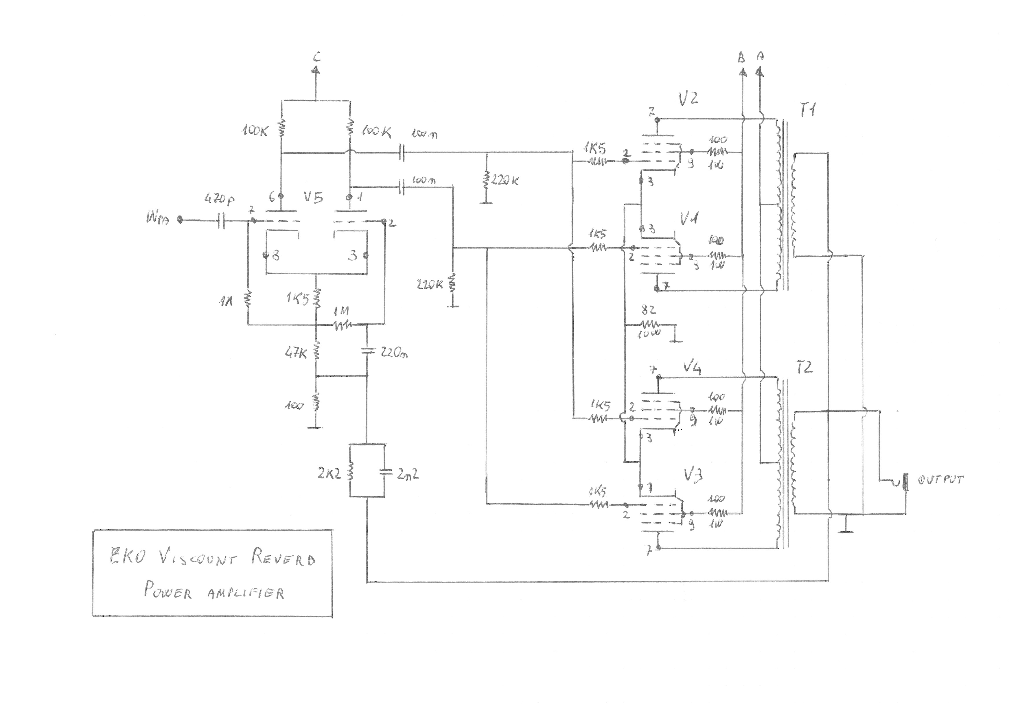
The signals coming from channel 1 and channel 2 preamplifiers are mixed at the input of this stage where we have a high pass filter, I suppose that is used not only to cut low frequencies, but also to compensate that funny behavior of the tone controls. The first amplification stage is a phase inverter (I call it a differential amplifier) whose outputs feed the output push-pull stages. We have an interesting implementation: instead of paralleling tubes two by two as it is usually done, here we have two identical independent output stages each using two EL84 and one transformer, the outputs of the transformers are paralleled. The output stage is pure pentode as in most cases (Vox, Marshall, Fender, etc.) and not ultralinear as in some Selmer amps of the same years. We also have negative feedback from output to input (the differential amplifier). It is quite a bit, so I suppose that this power stage has not a “soft clipping”, it keeps on singing at almost full power then it suddenly starts screaming. Vox AC30 and AC15 have no negative feedback. At the moment I can’t tell you exactly if the output tubes are class A or class AB biased, for sure they are not class B because for this class of operation a fixed bias is needed and in this amplifier automatic polarization is used; most likely, reading the datasheet and considering the cathode resistor value, the polarization should be for class AB operation. There is another interesting feature of the output stage: all cathodes are connected to a single un-bypassed resistor. Well this can be done with class A push-pull output stages because the current flowing in that resistor is constant all over the working range of the output devices, as a consequence also the voltage drop across it is constant and therefore there is no need for a bypass capacitor… in theory, because this works only for devices with identical characteristics and in real life this does not happen even in the case of a strict selection of the devices. In class AB the current is approximately constant only with small signals (i.e. a few watts at the output), with higher signals the output tubes alternatively switch off (this is how class AB works) and the cathode current is not anymore balanced, it keeps changing and so does the voltage drop across the cathode resistor. This leads to a local negative feedback that decreases the gain of the stage and, at the same time, increases the output impedance and, of course the damping factor of the output stage (the basses usually become muddy). That’s why in class AB and class B output stages for audio use a bypass capacitor is always used, even for class A ones. If you take a look at a Vox AC30 schematic you will find the capacitor (250uF). This capacitor is employed also in the Eko Herald, Duke and probably also in the Zodiac. In my amplifier there is no clue of its previous presence, as soon as I will have the amp back working I’ll make some measurements and listening sessions and I’ll decide if it is necessary or not; by the way there is already a 470uF 63V capacitor waiting on the desk! There is a suitable place for it, it looks like that this amplifier was engineered to have it but someone decided not to install it!
RESTORATION HAS BEGUN! – THE INSIDE
POWER TRANSFORMER
That’s how it looked before the plastic surgery.
After removing the case I had a surprise: the primary winding wires are OK…
… but not those of the secondary windings: look at the high voltage wires (two green and one red) almost completely without insulation! Also the low voltage wires (the yellow ones) are not in good condition.
No way! It can’t stay that way! I replaced and insulated those wires.
End of the job with the zinc painted shields replaced.